
An Experimental Plenoptic Camera
A standard 2D camera records only a flat projection of the 3D scene. It records the intensity of light rays striking pixels arranged in a 2D array. There is no information preserved about the way light travels from a point of the object to a pixel.
A plenoptic camera (also called light field camera) records a complete 4D light field of a 3D scene. Besides the radiance of a ray striking a pixel we also get information about the angle of incidence. Having this extra information we can calculate or render images at various distances from the lens. Changing distance between the lens and sensor (or film) is what we normally do to focus a camera. A recorded light field can be used to refocus an image by post processing.
The example images to the left are computed from the same single light field image. The example below shows that we can move a little bit to change perspective as well. Taking this further we can calculate a depth map or make a stereoscopic pair of images. And there is much more that can be done using this technique. For instance, if we know from where the ray bundles come we can block stray light or ghost images.
The resolution of my first images is not impressive. But they are produced by using home made micro lenses and the processing is not optimized. There is a lot of research going on in this field. By applying super resolution algorithms some scientists have been able to reach quite impressive resolution and image quality. Making the microlenses.
Light field cameras can be made in various ways. My camera is using the principles of the Plenoptic Camera 2.0. An array of micro lenses is mounted in front of the image sensor. Each micro lens produces a focused image of a portion of the scene. A specific point of the object is imaged by several micro lenses. Each one from a different angle.

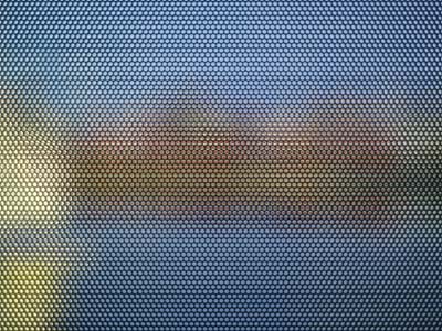
The unprocessed light field image
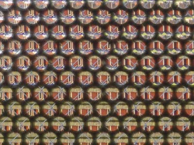
Detail of the light field image
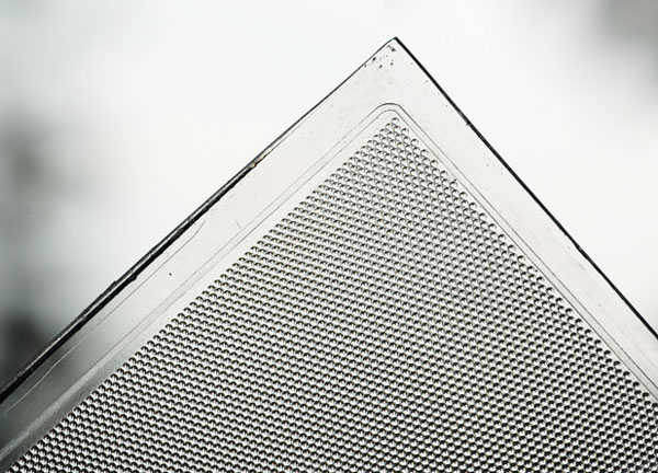
The micro lens array is placed in front of the image sensor.
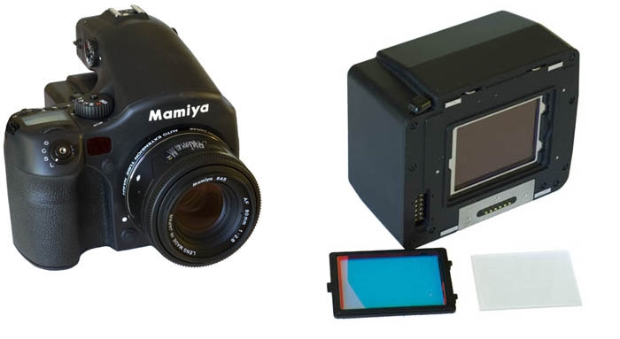
A Mamiya 645 AFD II with a ZD digital back was converted to a focused Plenoptic camera. It's really simple once you get the microlenses made. The microlens array is just dropped in between the IR cut filter and the sensor. There is a gap of about one millimeter where the lens array fits nicely
How to make a Microlens Array
When I decided to make a plenoptic camera it all seemed so easy. All you need to do is to add a microlens array on top of the image sensor in a digital camera. The only problem was to find a sheet of microlenses. After searching around on the Internet it was apparent that you cannot buy them like you can with bolts and nuts. There are some sources that keep them in stock but I could not find anyone that matched my requirements on size, focal length etc. There are companies that make perfect high quality lens arrays in glass on demand. But the cost is huge! You might consider buying a new car instead.
There just got to be a way to make them yourself. I soon found there was. I didn't expect the quality to be even close to those expensive custom made glass lenses. But would they be good enough to do some serious light field photography?
There just got to be a way to make them yourself. I soon found there was. I didn't expect the quality to be even close to those expensive custom made glass lenses. But would they be good enough to do some serious light field photography?
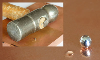
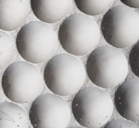
The idea is to place a ball bearing on a copper plate and smash it with a hammer. The ball bearing leaves a dent that will be used as a mold for a lens. The process just needs to be refined a bit.
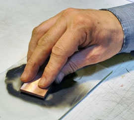
The copper plate is first heated until it is red hot to soften the metal. Then it is ground as flat and smooth as possible. The surface is then polished to a mirror like finish. This takes time and more time...
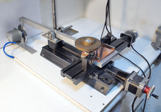
Small spherically shaped dents are created by hammering the little ball bearing on the copper plate. This is done in a Sherline mill. The mill column was removed and replaced by a beam. The beam is lifted by a cam mounted on a stepper motor. The ball bearing is fixed at the other end of the beam.
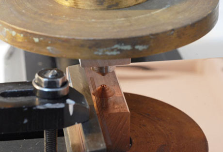
The ball bearing is seen mirrored in the copper plate's surface in the middle of the image.
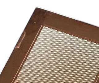
The finished tool has almost 6000 lens cavities on a 36x48 mm surface
The size of the ball bearing must be right in order to give a lens with the correct focal length. A diameter of 1.5875 mm (that is 1/16") turned out to be close enough for my design. Such ball bearings can be found in small bearings like the one used in hard drives. Don't take for granted that it has a perfect surface, inspect it with a microscope.
The refractive index of polycarbonate is 1.585. A lens surface radius of 0.79 mm then gives a focal length of 1.36 mm. A lens diameter of 0.48 mm makes the f-number 2.8. The depth of the tool cavity will then be 37 microns. It only takes a gentle tap to make such a shallow dent. The hammer weighs about 400 grams and is dropped from 2 millimeters height.
The copper is pushed away from the spot where the ball hammer hits the surface. It behaves much the same as when a meteorite strikes the ground. A rim is pushed up around the crater and there is a disturbance in the surface some distance away from the place of impact. This effect the neighboring cavities so there must be some space between the lenses. How much depends on the material, the diameter and the depth. Some degradation must be allowed as we don't like to have a very sparse array.
Next thing to do is molding a microlens array using the finished tool. I first tried molding Acrylic but had problems with the quality of the plastic. It was probably aged as it behaved strange when it hardened. After several attempts I gave up and started looking for another method as I could not get hold of fresh Acrylic. CD's are manufactured by embossing a delicate microscopic pattern into a sheet of plastic. I found out that they are made of polycarbonate. I made a crude test by just clamping a piece of plastic between the tool and a sheet of glass and left it in the kitchen oven for a while. It worked surprisingly well. But there were, as expected, air bubbles in many of the lenses.
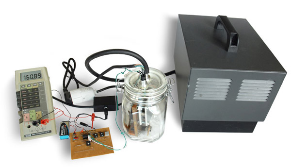
A small molding press was built i such a way that an even pressure could be applied. The polycarbonate sheet is sandwiched between the tool and a thick (4 mm) glass plate. The pressure is applied by eight strong springs. A heating element from a 100 Watt soldering iron was mounted on the tool. The thermostat is just some operational amplifiers that use a diode as sensor. One output is adjusted to give the temperature as millivolts so a DVM can be used to display the temperature. A triac is controlled by a MOC3041 that is an opto coupler with a zero crossing triac driver. It is perfect for isolating the low voltage from the high. The zero crossing function makes switching silent on the mains net. The molding press is placed in a vacuum chamber. It's made from a jam jar coupled to a refrigerator compressor. This particular compressor has been used by a repro camera hence the fancy box. But before molding there is one more thing to do. Polycarbonate plastic absorbs water to some extent. When the material is heated the water evaporates and causes bubbles or cracks. The solution is to dry it in hot air for 45 minutes before molding. The kitchen warm air oven set at 120°C worked just fine. The plastic sheet is then immediately clamped in the molding press and placed in the vacuum and the heat is turned on.
A small molding press was built i such a way that an even pressure could be applied. The polycarbonate sheet is sandwiched between the tool and a thick (4 mm) glass plate. The pressure is applied by eight strong springs. A heating element from a 100 Watt soldering iron was mounted on the tool. The thermostat is just some operational amplifiers that use a diode as sensor. One output is adjusted to give the temperature as millivolts so a DVM can be used to display the temperature. A triac is controlled by a MOC3041 that is an opto coupler with a zero crossing triac driver. It is perfect for isolating the low voltage from the high. The zero crossing function makes switching silent on the mains net. The molding press is placed in a vacuum chamber. It's made from a jam jar coupled to a refrigerator compressor. This particular compressor has been used by a repro camera hence the fancy box. But before molding there is one more thing to do. Polycarbonate plastic absorbs water to some extent. When the material is heated the water evaporates and causes bubbles or cracks. The solution is to dry it in hot air for 45 minutes before molding. The kitchen warm air oven set at 120°C worked just fine. The plastic sheet is then immediately clamped in the molding press and placed in the vacuum and the heat is turned on.

It takes 2-4 hours at 180°C for the plastic to float out properly. The time depends largely on the amount of pressure and the size of the plastic sheet. It turned out that the plastic does not come off the glass voluntarily. Putting the tool in ice water while it is still around 100°C hot cracks the glass plate and it falls off. Not so nice, but it works.
Just be very careful if you decide to try this! Strong mechanical forces, vacuum, heat, high voltage and glass - I can imagine a few terrible scenarios with those ingredients.
Just be very careful if you decide to try this! Strong mechanical forces, vacuum, heat, high voltage and glass - I can imagine a few terrible scenarios with those ingredients.
Copyright © Mats Wernersson