Movie Scanner
More than 50 years of family movies have piled up. There are Standard 8 mm, Super 8 and a lot of 16 mm footage slowly degrading and fading away. Some of the reels were transferred to VHS a couple of decades ago. But sadly they seem to vanish faster than the original film material. The quality of the VHS scans is not very good either.
So, why not make a scanner and digitize it all? It all seemed like a good idea. And it seemed easy and straight forward. But it turned out to be just a little bit trickier than I expected. The status right now is that all the 8 mm films are digitized. Next thing to do is to rebuild the scanner for 16 mm.
I decided to remake a flatbed scanner with transparency unit for several reasons. Photographic film has a quite high dynamic range, especially Kodachrome. Flatbed scanners can handle this high range well while a web camera or similar device cannot.
Another reason is that scanners can deliver uncompressed data which is more suitable for post processing than compressed data. Scanners are, despite the low cost, very advanced image recording devices.
They usually have TWAIN drivers that make the software programming feasible. But it all comes at the expense of speed. My movie scanner is slow. But who cares as long as the job is done automatically?
The philosophy behind the design is to make it easy to rebuild and modify for various film formats. I will probably scrap the whole thing as soon as all the films are digitized. Parts can be used for other projects.
It was necessary to rebuild and modify a lot as it didn’t work as expected to start with. The first mistake was to choose an HP scanner. Not bad scanners at all, but their TWAIN
support is terrible. Although HP has TWAIN drivers they don't support all the scanner functions!
Imagine that - the driver does not accept the standard TWAIN command for selecting the transparency unit. Back to the drawing board and back to the shop and buy an Epson scanner.
The optics of a flatbed scanner is obviously designed to cover the A4 format. Needless to say that the resolution is'nt that great for a Standard 8 frame of 4.5 x 3.3 mm. But the line array CCD has more than enough pixels.
So instead of using the original lens i replaced it with a 60 mm Micro Nikkor. Not the best choice either but good enough, especially at the center of the image and that’s what will be used.
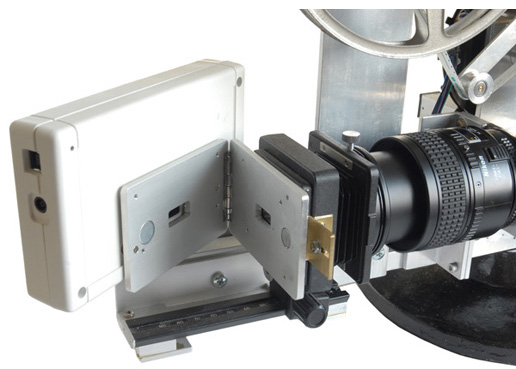
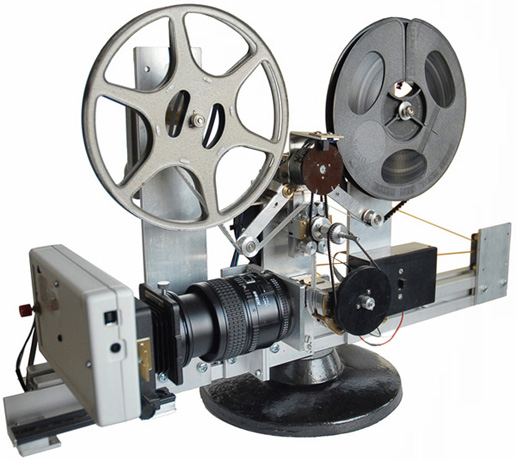
All electronics from the scanner was placed in this white box. The line array CCD is also in the box. It is mounted on hinges to facilitate focusing and alignment of the image.
The box can be adjusted in all directions to set the magnification and framing. Some parts from a slide duplicator are used to connect the lens with the CCD box.
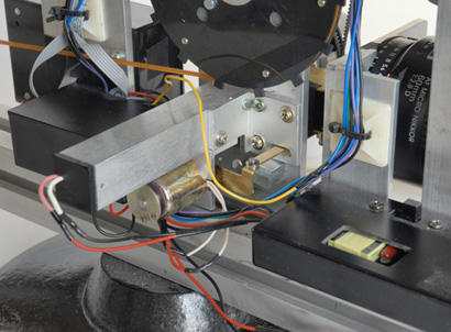
The electronics cannot be used straight off. The microprocessor controls a stepper motor that pulls the carriage. A photo interrupter reads the home position of the carriage. To manipulate the behavior I put a microcontroller between the scanners microprocessor and the stepper motor driver circuit. I just tell the microprocessor what it expects to hear while controlling the stepper motor my own way in the background.
The box can be adjusted in all directions to set the magnification and framing. Some parts from a slide duplicator are used to connect the lens with the CCD box.
The electronics cannot be used straight off. The microprocessor controls a stepper motor that pulls the carriage. A photo interrupter reads the home position of the carriage. To manipulate the behavior I put a microcontroller between the scanners microprocessor and the stepper motor driver circuit. I just tell the microprocessor what it expects to hear while controlling the stepper motor my own way in the background.
The film runs through a curved gate. The gate moves while scanning. It is easier to obtain a smooth and precise movement of the gate than just pulling the film. When a strip of ten frames has been scanned then the gate returns and the film is advanced.
One more thing need to be fixed. The flatbed scanner starts each scanning with a calibration procedure. This is good as it improves image quality. But the problem is that is calibrates towards the transparency light box where there are not supposed to be any film. Not easy when the film is hundreds of feet long.
The light source is a fluorescent tube - much longer than it need to be. But the scanner's software expect this light source so it would not be wise to replace it with a more convenient white LED. It was placed inside a square aluminium tube with an opening just behind the film gate.
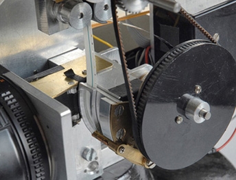
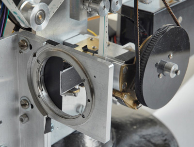
A periscope with one of the mirrors foldable redirects the light around the film during calibration. The solenoid that swings the mirror can be seen under the square aluminium tube that houses the light source.
The mirror can be seen folded away in the center of the lens bayonet mount.
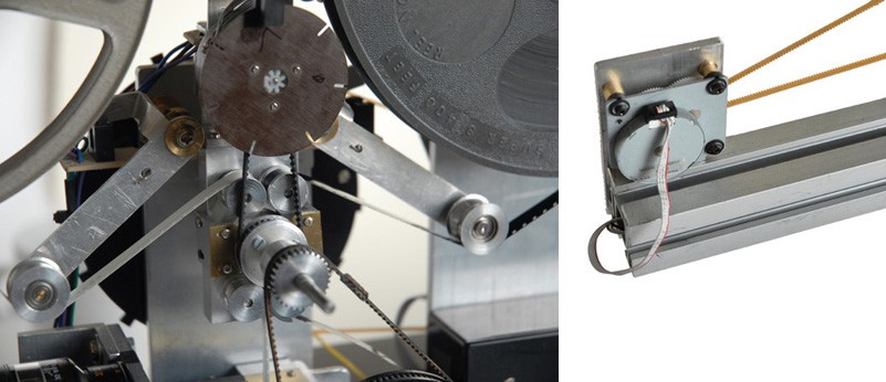
The film is advanced by a central sprocket driven by a stepper motor. Although it is a stepper I also have a photointerrupter and code wheel to assure alignment. The film wheels are driven by two separate DC motors. Photointerrupters keeps track of the film slack. The original Epson stepper motor seen to the right drives the film gate. The belt is long so the motor had to be placed far away...
Copyright © Mats Wernersson
Copyright © Mats Wernersson
Copyright © Mats Wernersson
Copyright © Mats Wernersson
Copyright © Mats Wernersson